How to make a Unit which will extract information about the quantity of water present in the tank?
Let’s move on to the designing part in which we will first design the circuit and then do the conversion from A/C 240V to the regulated 5V for operating the circuit.
Step 1: Collecting The Components.
The components used in this project are easily available in the market.
Step 2: Setting Up The Apparatus.
Now, that we’ve collected all the components let’s assemble them and design the circuit.
Step 3: Working Principle.
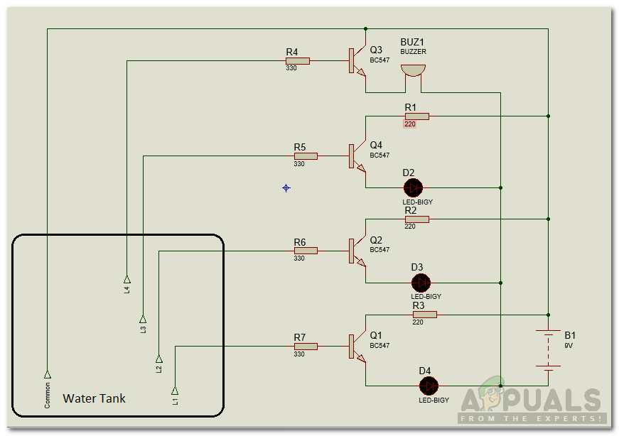
Among all the components the most important components are Transistors BC 547. There is a total of 7 transistors and they will be sensing the water level. LED’s will be monitoring the water level in the tank and the functionality of each LED is explained below : Presently, as the water ascends the sensors begin to get in contact with the water and the transistors are activated and there is a progression of current in the transistors making the LED’s light up. There is a current limiting resistor involved between transistor and LED and it prevents higher voltage to destroy the LED. LED’s light up from Red to Yellow and then Green and finally Blue, thus making a sound.
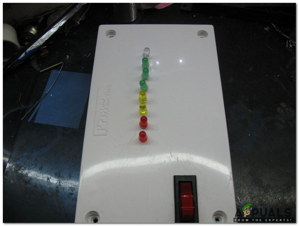
Step 4: Putting the Circuit in a Box.
We need to put the circuit in a small box and make holes in it appropriately so that LED’s may come out of the box easily. Then cut the plastic board for the Power Switch. Take a PCB board and solder the LED’s on it according to the levels defined above. Stick the buzzer behind the PCB board and also fix the power supply by taking care of the transformer. After analyzing the circuit we came to know that five supply lines need to be taken out from the main circuit board to the sensor. Four lines are of the sensors and one is for Common Positive Pin.
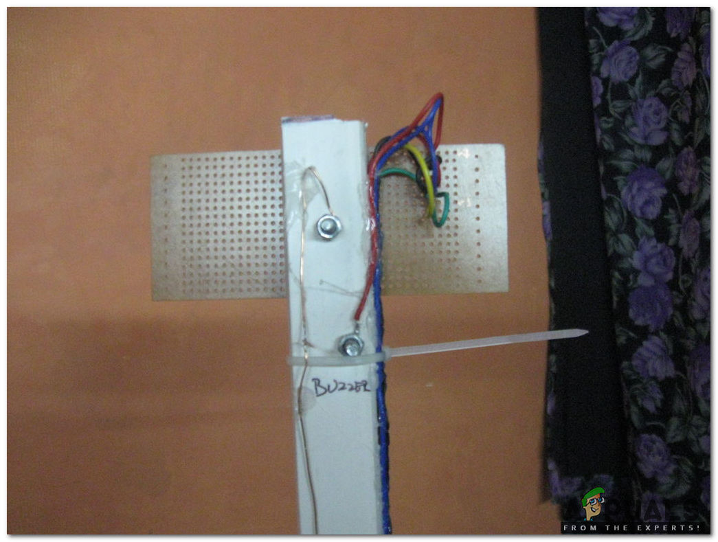
Step 5: Designing Sensors.
We possibly need to make two channels so when they are in contact with water they will go about as a switch, as water is a good conductor of electricity. We can use a PVC pipe and make holes in it. Firstly, measure the height of the tank and then with equal intervals mark 4 points on it. Make holes on those points and then make a loop of wire which will be carrying the current. Fix that loop of wire with nuts and bolts in that PVC pipe and afterward add a common wire to the casing. The hole of the bare wire and bolt should be kept a minimum and in the event that you need, you can solder a little bit of wire to the common line just next to the nut and screw as the sensing would be more at the point when the water interacts with the normal wire and the bolt, there will be transfer of current from the stripped wire to the bolt and hence, the sensing part is complete.
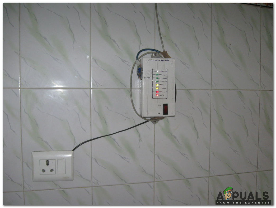
Step 6: Installing the Designed Prototype.
Finally, we will install the device into the tank. Firmly fix the rod inside the tank and make sure that the rod (PVC pipe) touches the bottom of the tank. Presently for the establishment of the gadget, we should locate a reasonable spot for a clear view of LED lights. Choose that place which is out of reach of children and from where you can easily turn ON and OFF the switch. We will screw the two L hooks to the device and fix it into the wall and afterward take A/C 220V from any socket and give it to the board. We have successfully installed the device and it is indicating the water level in the tank. We can observe that LEDs are glowing and the topmost blue LED will glow when the tank is filled thus, turning ON the buzzer.
How to Automate Your Sprinkler Control to Detect Weather conditions Through…How To Detect Rainfall Using Rain Sensor?How to Detect Host Outages using Ping Monitor?[Fix] ‘Windows could not automatically detect this network proxy settings’